
Jump to:
Basic Calibration Setup
This section will walk thru the process of getting a base cal setup. For most users, following these instructions will get you to a 90% cal. For many users this will be good enough. Others should follow up with the ‘Fine Tuning’ section to understand datalogging and how to use it to fully tune in the cal.Edit
Chapter 1 – Calibration configuration
Edit
1.1 – Getting ready
- Download and install MP Tune. You can get it here.
- Download and unzip one of the Turbonator code bases. You can get them here.
- T/GLHS – for the ’86 GLHS or other cars running L-Body type wiring
- T/LM – for the non L-Body T2 LM cars (’87)
- T/SMEC – for cars equipped with a SMEC (’88-89)
- T/SBEC – for cars equipped with an SBEC (’90-91)
- T/TIII – for TIII cars, (’91-93) with SBEC or SBECII
- Early Log T1 cars – there is no Turbonator cal for these vehicles.
- Open the zip file and copy all of the files to a folder you intend to use to keep your tuning files in.
- If you decide to put your template file in a unique folder from the ‘base’ templates, make sure to copy the .asm file into the same folder. MP Tune will look for it there; if it doesn’t find it it will prompt you to tell it where to look.
- Wait, what is a Template file anyway?
- Pick a template to use.
- Picking a template to use is pretty simple. There are usually only minor differences from cal to cal. If possible, pick the template that matches your cars original calibration. If in doubt, just pick a template that matches your car setup (ECU + displacement + trans type).
- The 3 digits you see in the file names are the same as the last 3 digits of the (stock) ECU PN. Or, the Calibration ID of the factory cal. These templates contain the stock cal data from those ECU’s.
- There are also pre-made BoostButton ‘Stage’ cals available for download and use. These cals have some generic setup already performed on them (such as injector/MAP scaling, timing and boost control). One of these may also be a viable starting point for your tuning efforts.
- If you want to run AC, you should also pick a template that has AC enabled already. Turning on the AC function is not as easy as simply enabling the option flag.
- Copy the chosen template and re-name to something meaningful to you.
- Open MP Tune, and open the template file you just copied.

1.2 – Configuration Flags
The configuration flags set the cal to enable various features of the code. There is 1 factory config flag register, and 2 Turbonator Option registers.

- Select the options you wish to enable.
- Be sure to hit ‘save’ when finished.
| If you wish to use an auto transmission, select a template that has that enabled and calibrated in the template. It’s much more involved to convert a cal to auto than simply selecting the option. Many calibration values (idle control, as a primary example) must be changed in conjunction with the flag. |
|---|
| Similarly, if you wish to enable AC, be sure to choose a template that already has it enabled. There is much more to enabling AC than just the option flag. There are many calibration values that need to change for AC to work correctly. In the cals that did not have AC enabled, these are not necessarily set from the factory. |
For more info on what the Turbonator options can do, see the Turbonator codebase explanation.Edit
1.3 – Basic MAP and Injector Scaling
One of the main advantages of MP Tune over it’s predecessors is that it can more easily scale the calibration for MAP or injector size.
The template contains some data that allows MP Tune to scale those tables for MAP size and injector size. To see a list of the affected tables, select the ‘Tables’ item under the ‘Scaling’, ‘Injectors’ submenu. To see what tables are scaled for MAP, select the ‘Tables’ item under the ‘Scaling’, ‘MAP’ submenu.
- To scale for Injectors, select ‘Scaling’, ‘Injectors’, ‘Size’, and then your injector size.
- To scale for MAP, select ‘Scaling’, ‘MAP’, ‘Pressure’, and then select the appropriate MAP range.
- MP Tune will scale all of the tables listed by the appropriate method automatically.

- If your injector size is not shown in the list, select ‘Setup’, ‘Injector Sizes’; a menu will come up.
- Press ‘Add’, then input your new injector size, and hit ‘Save’.
- You will need to re-load your template for the new injector size to be visible in the list.

Chapter 2 – Fuelling Setup
2.1 – AFR Setup
2.1.1 – 2D Cal (T1/T2) Setup
Using MP Tune, you can easily set the ‘target’ AFR at any MAP setting. The ‘target’ AFR in this case refers to the AFR used to calculate the theoretical injector pulsewidth at a given MAP setting. It is not a target for the ECU to try and reach via O2 or WB feedback. For more detail on how the Chrysler code calculates the PW, see the fuel tuning section.
The AFR guidlines and setup is important at this point. You will need it later when you start to fine tune the PefTbl. MP Tune has a utility that can take in logged AFR, MAP, and RPM data to help you fine-tune the PefTbl when needed.
MP Tune will draw yellow ‘guidelines’ (seen in the screenshot) in the background of the 3 main fuel tables to represent the calculated AFR that you input. To setup the AFR guidelines, select ‘Settings’, ‘AFR Settings’.

This will open the AFR guideline editor. The MAP axis is in absolute; so 0psi = -14.7psi (vacuum). Set your desired AFR for each MAP point. If you want to make a straight line between 2 different AFR settings, use the ‘INT’ button on the menu to interpolate between the 2 points. Also be sure to set the engine and fuel parameters on the right side of the editor. These are just as important to the AFR setting as the injector size (the AFR calculator takes the injector size from the cal setup, you don’t need to input it here).
- The 3 main fuel tables are not directly affected by this guideline. MP Tune leaves it up to the user to move the table breakpoints to match the guideline, if you choose.
Turbonator cals should come with the AFR settings pre-set to be 13.6 in vacuum @ WOT, ramping to 11.5 in boost (as shown below). Part Throttle is set to 14.9 in vacuum, and matching the WOT table in boost. The baseline table usually doesn’t need to be edited as it is only used at idle, and the adaptives control the AFR.

| TIP | If you’re running an Intake Air Temp Sensor, it is probably best to set the intake air temp to 90C. This is the point in the IAT compensation table where the enrichment is zero. |
|---|---|
| If no IAT is installed, then you should use 60C. It may seem counter intuitive, but if you set it up this way, your engine will be protected for the lowest possible intake temp, and will run slightly rich when the temp is actually hotter than this. |
| TIP | You can copy/paste data to and from Excel into the AFR data table. You can also use the ‘Int’ button to interpolate between 2 AFR values. For example, if you want a straight line from 15psi and 12.5AFR to 30psi and 11AFR |
|---|
- Once the AFR Guidelines are setup as you want, you can edit the 3 main fuel tables (FuelBaselineFromMAP, FuelFullThrottle, and FuelPartThrottle) to match the guidlines.
- Be sure to save when you’re done before moving on to the next edit (MP Tune has an ‘undo’ feature but it currently will ‘undo’ everything until your last save, not just the last edit).
- The purple line represents the 80% Duty Cycle @ 100% PumpEff and is provided as a reference so that you have an indication of how much of your available fuel is being used.

2.1.2 – 3D Cal (TIII) Setup
This is much more complicated and will require a very detailed explanation. TBC.
2.2 – BatOff Setup
The BatOff (FuelBatteryOffset) table represents the injector latency. The injectors are an electro-mechanical device. As such, they need time to open and close. As they are opening, they do not flow the full amount of fuel. The latency is the amount of time after the injector is powered, until it can be considered to be flowing at full rate. This open/close time is then added to the total Injector pulsewidth to compensate for the loss in flow.
The latency is mostly dependent on battery voltage; though it can also vary with fuel pressure (That’s why it’s best not to stray too far from the manufacturers fuel pressure rating for an injector).
For stock injectors, of course the table needs no adjustment. Even for +20’s, the stock BatOff table seems to work well. For +40’s, I recommend scaling the table by 40%-50% (right-click on the table name; then select ‘Scale Table’). Or, simply copy the BatOff table from the S60 template (which uses +40 injectors). Other injectors you should try to get the latency from the manufacturer. There are also latency tables published on the internet for various popular injectors. Guessing at the latency is not a good idea. As you can see, the latency is on the order of 2mSec at normal battery voltage. For very large injectors (72pph+), this may be very close to the total required PW for idle. In that case, you can imagine that a small error in the latency can result in a big change in actual idle fuel.

2.3 – PefTbl Setup
The PefTbl (PumpingEfficiency) is the table used to compensate for the differences in flow vs. RPM. It is similar to, but slightly different from, the Volumetric Efficiency used by other engine control systems (For details on how the Chrysler PefTbl is different from a typical VolEff table, see the detailed fuel explanation).
For a stock head/intake; or even for a very mildly ported head, you shouldn’t need to touch this table until you have some AFR data you can use to re-tune it.
The 3 Main fuel tables are calculated based on 100% Pumping efficiency. That is, the PW calculated assumes that the engine will pump it’s full displacement every revolution, regardless of engine speed. But, in reality, the engine cannot pump is complete displacement due to flow losses in the throttle, intake manifold, intake and exhaust ports, and exhaust manifold. This flow loss is heavily dependent on RPM. The PefTbl represents this flow loss and allows the ECU to reduce the amount of fuel injected accordingly.

Porting Effects
It’s almost impossible to say exactly what effect porting a cylinder head or intake/exhaust manifolds will have on the PefTbl without testing and hard data.
In general, though, porting will increase the flow at higher rpm, but can reduce flow slightly at low RPM. The effect on the PefTbl is to ‘rotate’ the table counter clockwise; generally about the peak. In my experience, a basic ported head will move the PefTbl up about 5 percentage points in the highest RPM (~6k), and drop it about 2 points in the low RPM (~2k). Heavily modified heads or custom intake manifolds with significant changes in runner length will have a much bigger impact. How tune re-tune the PefTbl using real measured AFR data will be covered in a fine-tuning article later.
Example of a typical ‘rotated’ PefTbl. The dotted line is the new position; while the thin line is the original.

WB O2 Sensor Use
Turbonator cals for the SMEC and SBEC can be setup to use a WB signal input instead of the NB. Basically, the ECU emulates the NB signal internally for use in the feedback control. However, using the WB in this way allows you to log the actual WB AFR using MP Scan and sync that data with RPM and MAP. This data will be very useful later for tuning in the PEFTBL using the PEFTBL Tuning tool built into MP Tune.
It’s a more advanced topic, but if you wish to enable this feature in your ‘base’ cal to make tuing easier, check this article – WB2NB Setup. red link means the article isn’t written yetEdit
Chapter 3 – Ignition Timing Setup
For ignition timing, MP Tune scales all of the relevant tables for MAP for you. So, there’s actually very little to do in terms of setup (before you really start tuning).
There is 1 adjustment I recommend making to the timing before you run the car at higher boost – reduce the timing in high boost. This is really just to be safe. While MP Tune can scale the tables for MAP, it won’t make any adjustments for you. So, with no adjustments for higher boost, you will have the same timing at 29psi boost that you previously had at 14psi boost. That’s probably not realistic for most applications.
There are only 2 tables that need to be adjusted – AdvanceFromMAPWarmFull and AdvanceFromMAPWarmPart.
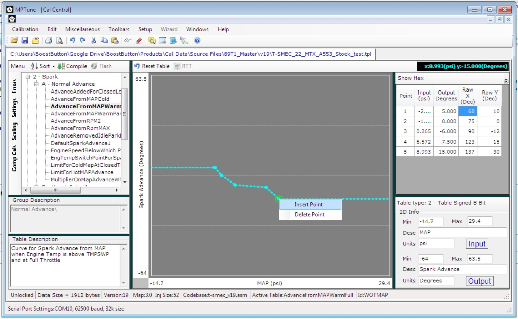
To add a data point to each table (AdvanceFromMAPWarmFull shown, but do this to both tables):
- Right-click on any existing data point and select ‘Insert Point’ from the pop-up menu.
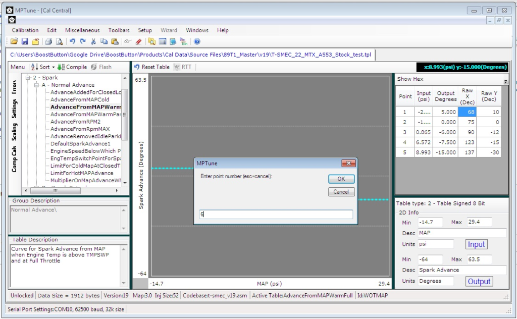
2. Enter the number that is 1 higher than the last point in the table list to the right (In this case, the highest point in the table is #5, so enter ‘6’).
3. Move your new data point to at least 20psi, and remove 2-4degrees of timing (it’s just a guess at this point).
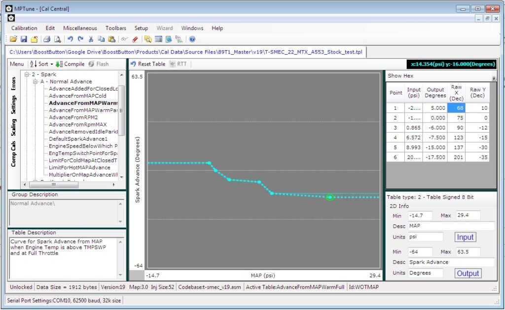
4. When you’re finished, hit ‘save’ to save your data and you’re all done.
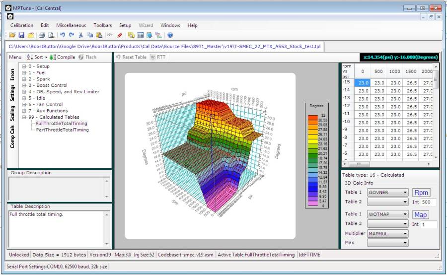
One more note about the ignition timing in MP Tune. MP Tune has a feature that will combine the relevant tables and show you the total timing map in 3D (Timing Vs. RPM and MAP). These tables are not editable, they are just a representation of the timing of 3-4 (depending on the code version) different tables that combine to give the total final timing.
As you can see in the calibration below, the total timing in boost and at high RPM is 16 degrees. Always use the 3D tables to check your total (final) timing in boost. For most engines, total timing between 16 and 22 degrees (depending on fuel octane, combustion chamber, etc.) will be about right.
Chapter 4 – Boost Control Setup
Chapter 5 – Overboost, Rev, Speed limiter setup
All of the stock-type limiters in the Turbonator calibrations use the factory fuel-cut logic. They are all basically the same limiters, just triggered by different events; such as Overboost, Rev Limiters, Speed limiter, or one of the various limp-mode limiters.
Overboost
Overboost control is used to prevent the engine from going too far beyond the intended boost range and causing engine damage.
There are 4 overboost constants:
list names and uses, show a screenshot
To effectively turn off overboost completely, set all 4 values to the maximum.
Rev Limiter
The main rev limiter has 2 values; a fuel ‘Off’ value and a fuel ‘On’ value. The ‘On’ should always be lower than the ‘Off’ setting. Set the values closer together to hold the RPM more precisely.
There is no way to effectively turn off the rev limiter. The maximum setting is 8160rpm. This is the highest RPM that the ECU can calculate.
Speed Limiter
The Speed limiter is only available in the SMEC and SBEC and later. The LM has no speed limiter.
Similar to the rev limiter, the speed limiter has a fuel ‘Off’ and a fuel ‘On’ value. The ‘On’ should be set lower than the ‘Off’ setting. There is no way to turn off the speed limiter completely. But, if you set both values to 254, it will effectively be turned off (unless you have a FWD Chrysler that can actually go that fast).Edit
Chapter 6 – Fan Control
Fan control setup is fairly straightforward. If you are ruining a stock thermostat; there’s no reason to change anything here. If you are running a 185F or 180F thermostat, you will likely want to reduce the fan on/off temperatures accordingly to get the full advantage of the lower thermostat temperature.
The fan operation has 2 different settings: Low speed and high speed. There is an on and an off setting for each speed range. The ‘on’ temperature should always be higher than the ‘off’ temperature. Otherwise, the fan will never come on. For example, at high speed, the fan turns on at ~220F and off at 195F.
There are also settings to turn on the fan when boosting. For the stock T2 setup, this was intended to improve the efficiency of the intercooler by preventing any reverse flow through it.
pic of fan settings in MP TuneEdit
Chapter 7 – Compile into binary
The very last step in creating a base cal is to compile the cal into a binary file. The binary file is the file that is actually used by the ECU (see here for more info on file types).
Simply press the ‘compile’ button in the MP Tune editor window. Your template file is saved, and a .bin will be created using the same file name (my_cal_file.tpl becomes my_cal_file.bin).
You are now ready to load the .bin file into your ECU either by flashing, or burning a chip.